Cable, electrical components, new switches
£A lot
Screwdrivers, Ratchet crimpers, side cutters

The electrical design is loosely based upon the original series III wiring and uses standard series III parts rather than the military relays, flasher units etc.
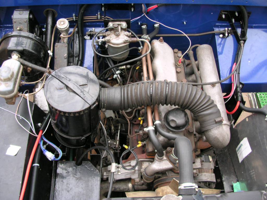
A tube runs down each wing individually allowing engine electrical components to be picked up from both sides of the bay at various drop off points.
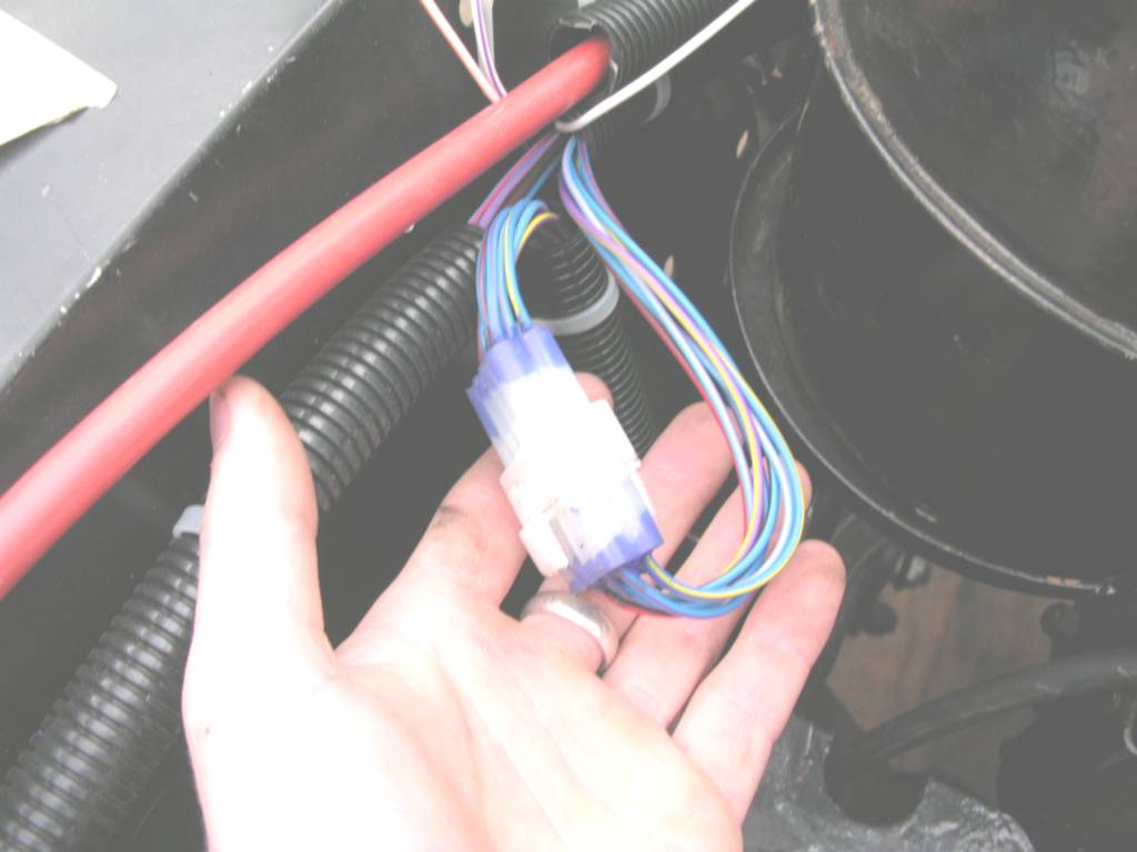
This picture shows a break in the tubing to enable the cables to be routed from the dash to the lighting, rear of the vehicle or drop off to service the engine. On completion of the electrical work the tube ends will be filled with sealant to keep out moisture.
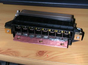
This created a problem in that I needed to bus together all the input sides of the fuses as I couldn't find a fuse block with a common input.
I tried linking together all the space terminals with solid copper wire but wasn't happy with the result. I also wanted the input cable to be securely fastened as it is quite large in diameter.
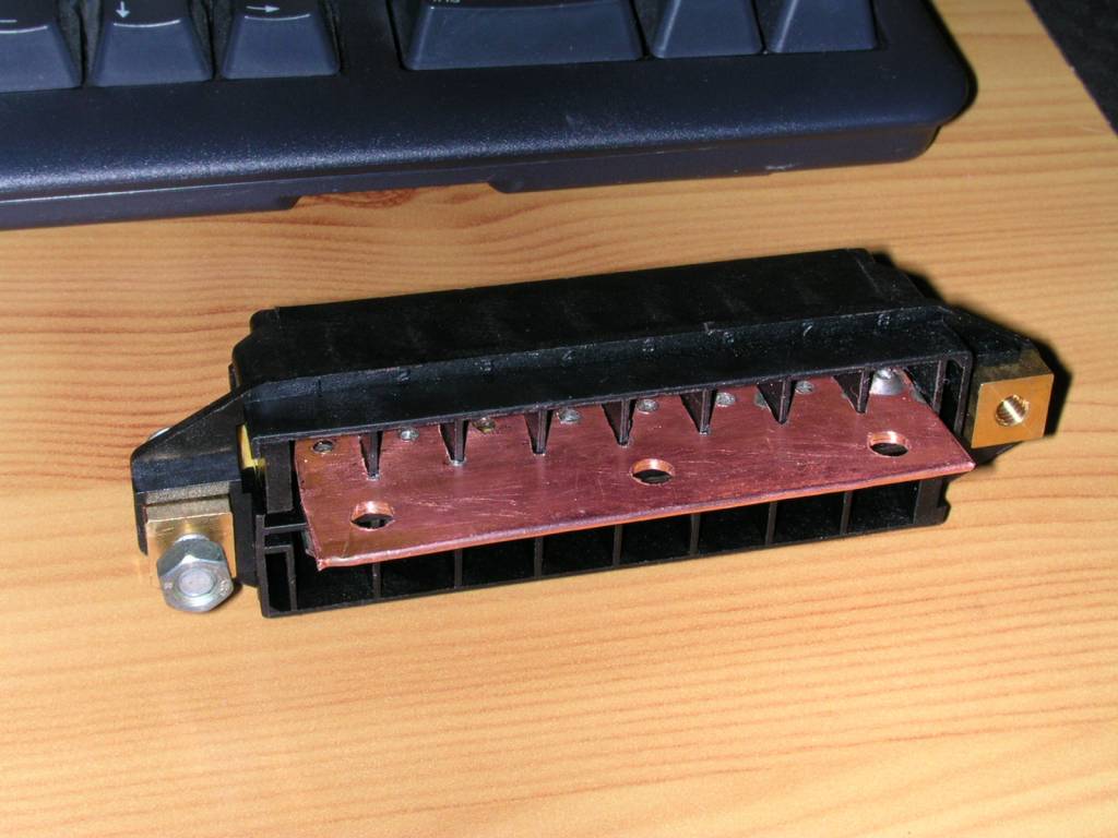
I made up the commoning bar out of some flattened 15mm copper heating pipe, which i folded over to half the length to give me a thicker mounting area. Using a blowtorch I then warmed up the copper and soldered the terminals onto the bar.
It took a lot of time and patience to make but I think it will be worth the result. I just need to find some sort of sleeving to help insulate the bar but the cable will be fastened to it using a ring crimp and a small nut and bolt with shakeproof and spring washers for a good contact.
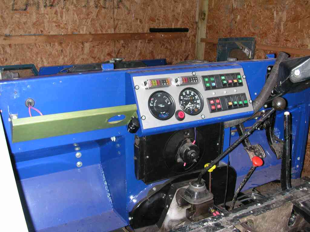
The green section on the left will eventually form a new storage area and a similar item will be fabricated for the drivers side which will mount around the steering column.
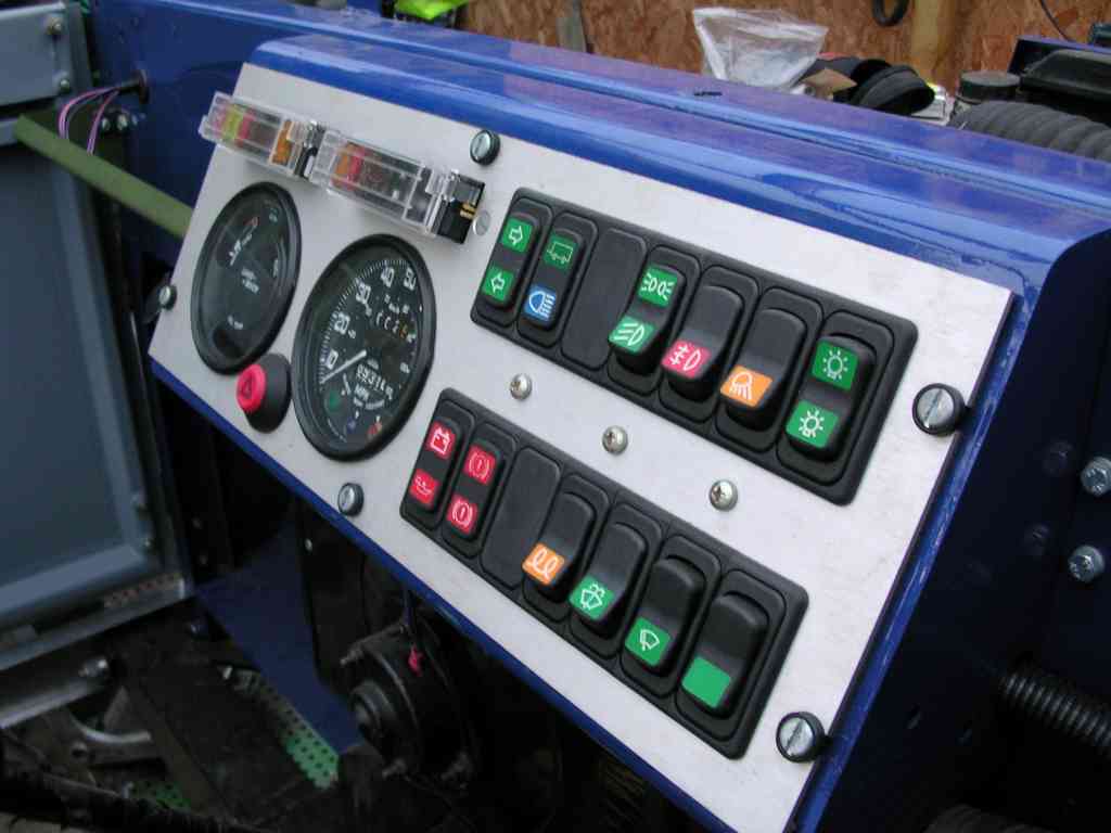
The fuses are included on the dash for ease of access and I'm thinking of using indicator fuses that light up if they've blown.
The switches were expensive but they look quite good and there's still room for a bit more expansion.
..Click here for the latest revision of my electrical diagrams. Now in PDF format.
Dashboard installation pictures